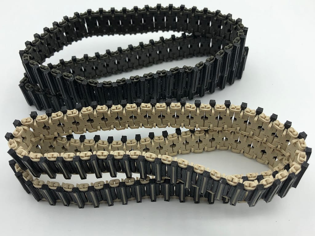
Chain Link Track Design
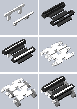
Four different parts are combined to create this track. These images from the 3D models show how they go together.
- For the plates and studs (colored white here) we use a relatively rigid material, such as ABS or ASA.
- We like nylon for the links (light gray) which need to have a low coefficient of friction and enough flexibility to resist fracture.
- The treads (dark gray) need to provide traction on smooth surfaces, so we use a TPU, such as NinjaFlex.
Chain Link Track Assembly
Each track needs a minimum of 41 segments. A segment is composed of one plate, two links, one stud and one tread. For ease in seeing details in these photos, we used parts with lighter colored and/or more translucent materials than those supplied with our kits.
- The plate has a smooth, flat face, which will face the exterior of the track (away from the wheels), and an obviously rougher, more rounded face. If you are familiar with FDM 3D printing, you will recognize that the smooth surface was the one on the 3D printer’s build platform during fabrication.
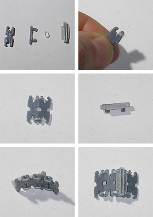
- To begin assembly (see upper right photo), pinch two plates together with their smooth sides outward, and rotate a link onto the prongs as shown. Similarly place another link on the opposite side of the track, then unfold the two plates to prevent the links from slipping off (see middle left photo).
- The stud and tread are combined by inserting the stud into the top of the tread so that the stud prongs protrude through the bottom of the tread and the stud top is slightly recessed into the tread (see middle right photo).
- After you have several plates linked together, you can start pressing the stud-tread subassemblies into the notches in the plates (see bottom row of photos). We like to assemble an entire track’s worth of plates first, checking as we go that the track is smooth and flexible. Due to variations in 3D printer calibration, sometimes there may be enough “elephant foot” expansion effect on the smooth face of the plates that the tracks will be too tight and rigid. If that happens, we can sand those edges until the tolerances are adequate.
- For the standard “gasoline powered” appearance of the model, where the rear idler is positioned low to the ground, 41 segments make up one track. The range of adjustment in the idler arm allows for a track length of up to 43 segments. So, add one or two more segments per track if you desire a higher idler position. This can be good for climbing obstacles when reversing.