Difficulty:
3D Printing
Medium
Assembly
Medium/Hard
Electronics
Easy
3D Printing
3D print the following parts:
| Quantity | Part |
| 1 | Base Plate |
| 2 | Conduit |
| 1 | Face |
| 6 | Femur Slide |
| 6 | Femur Yoke Sleeve |
| 12 | Femur Yoke |
| 6 | Femur |
| 4 | Gear 18 Teeth Idle |
| 2 | Gear 30 Teeth Drive |
| 4 | Gear 30 Teeth Idle |
| 1 | Hardware Cover |
| 1 | PCB Clip |
| 4 | Plate Spacer |
| 6 | Tibia Wide |
| 1 | Top Plate |
Assembly
Prepping the Femurs, Base, Faceplate, and Gears
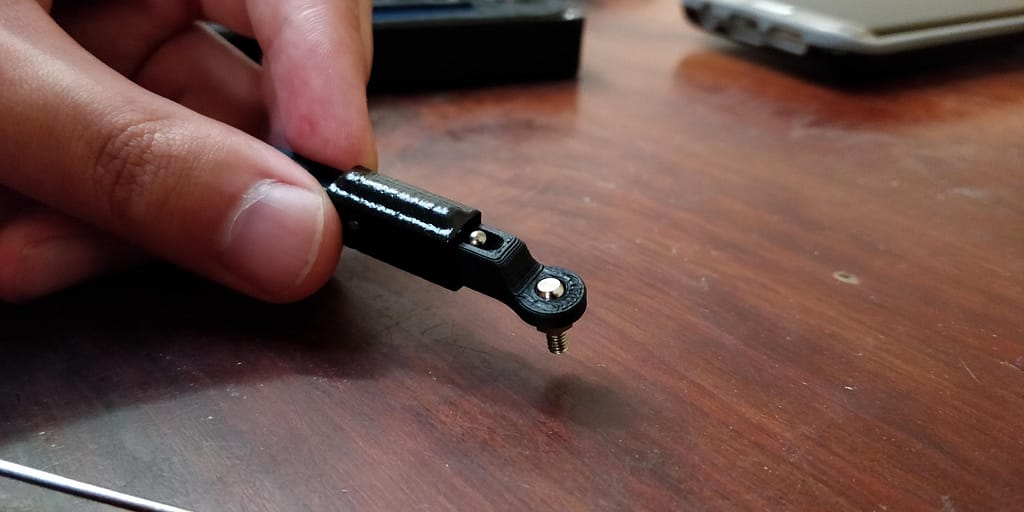
Femurs
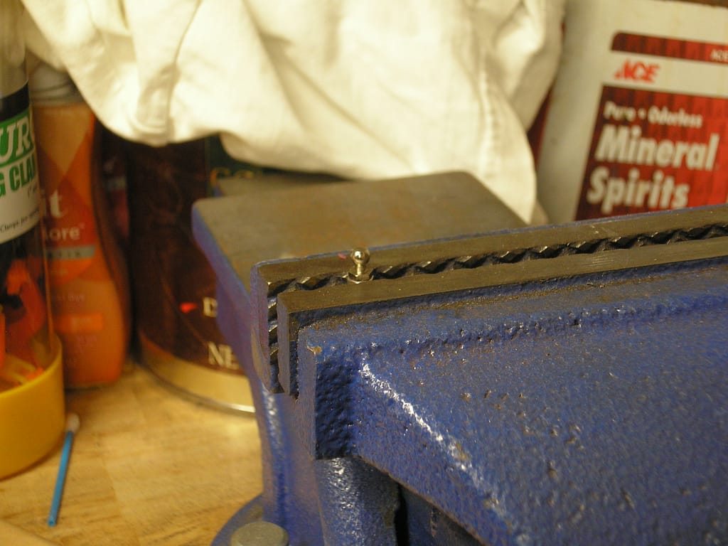
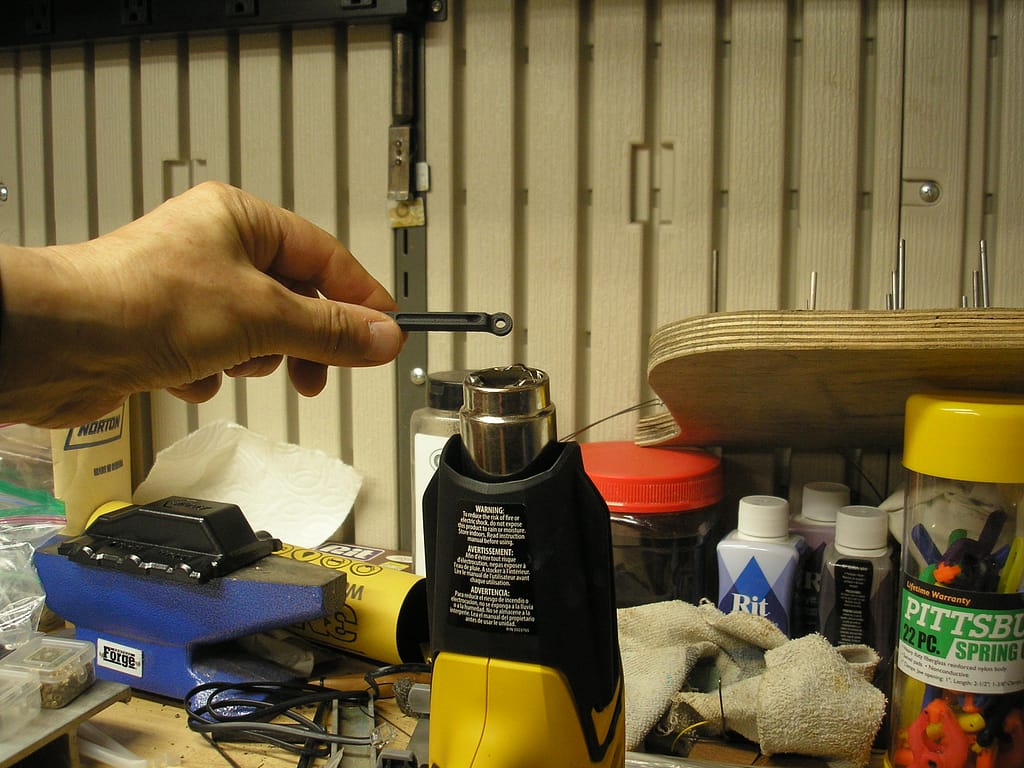
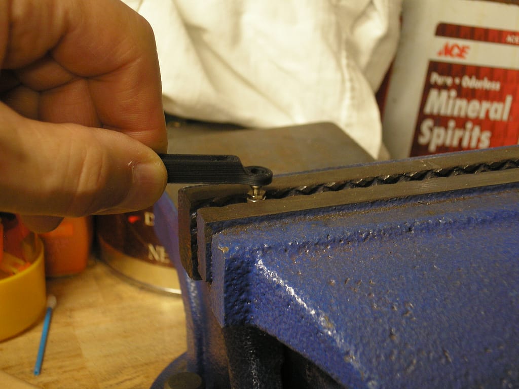
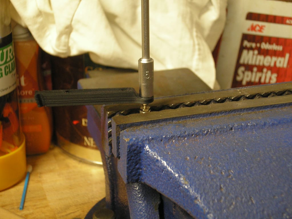
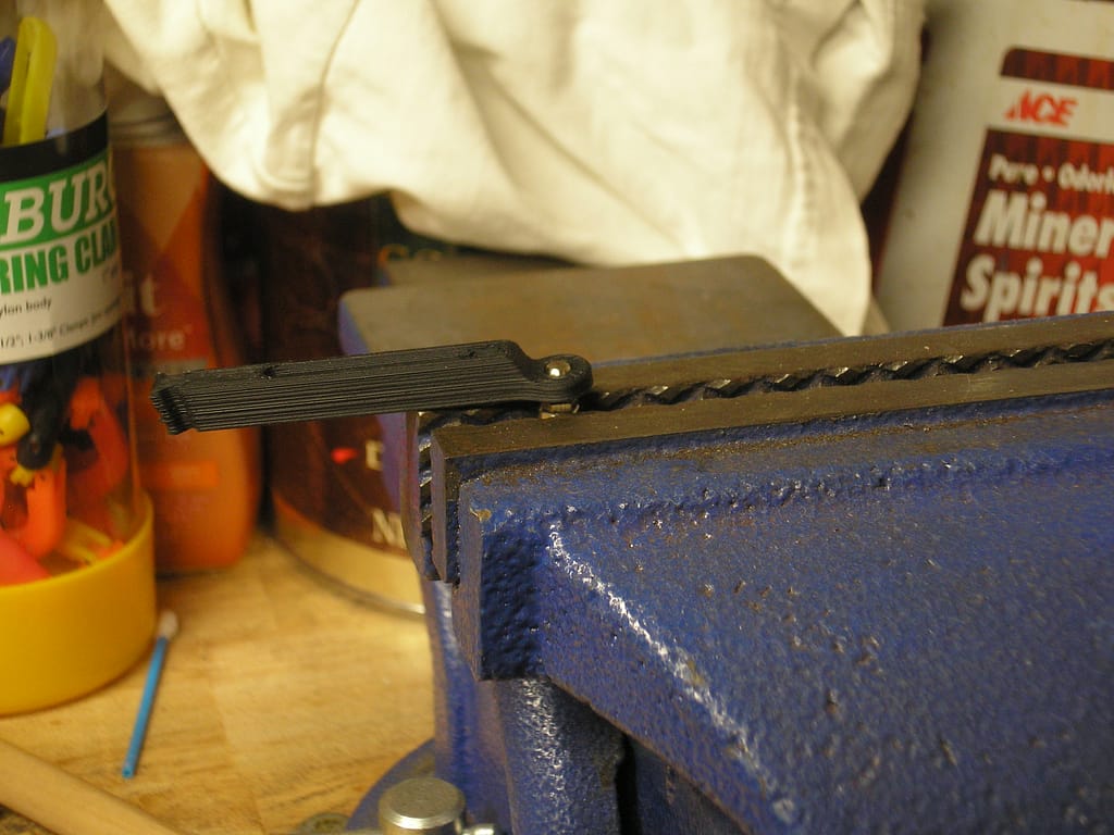
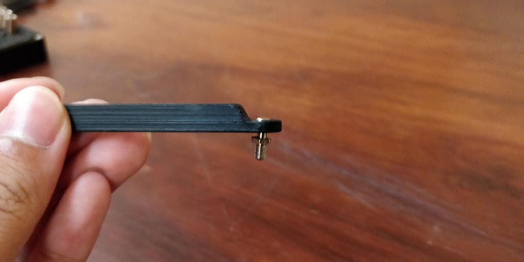
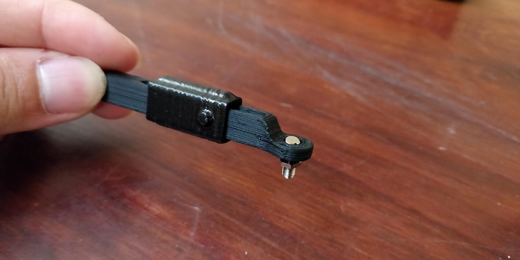
Start by using a heat gun and heat the hole on the femur. Make sure to keep the heat gun on low and a safe distance away from the femur. Only heat the hole of the femur enough to loosen the plastic just enough to insert the ball stud. Insert the ball stud, ball side up, into the femur hole from the bottom side. Use a socket screwdriver to apply even pressure when pushing the femur into the ball stud.
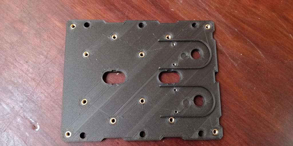
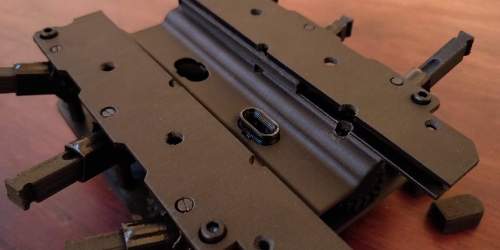
Baseplate
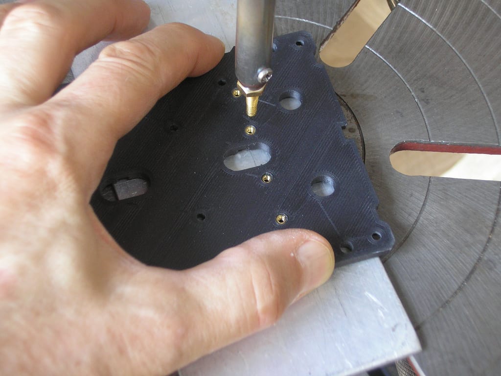
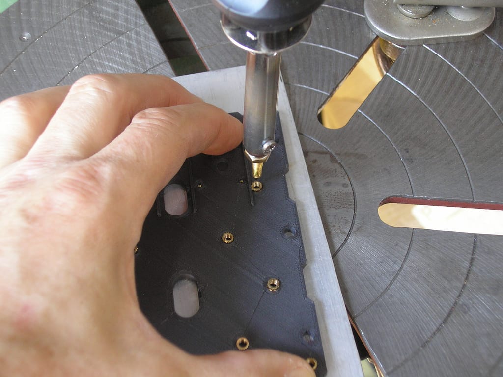
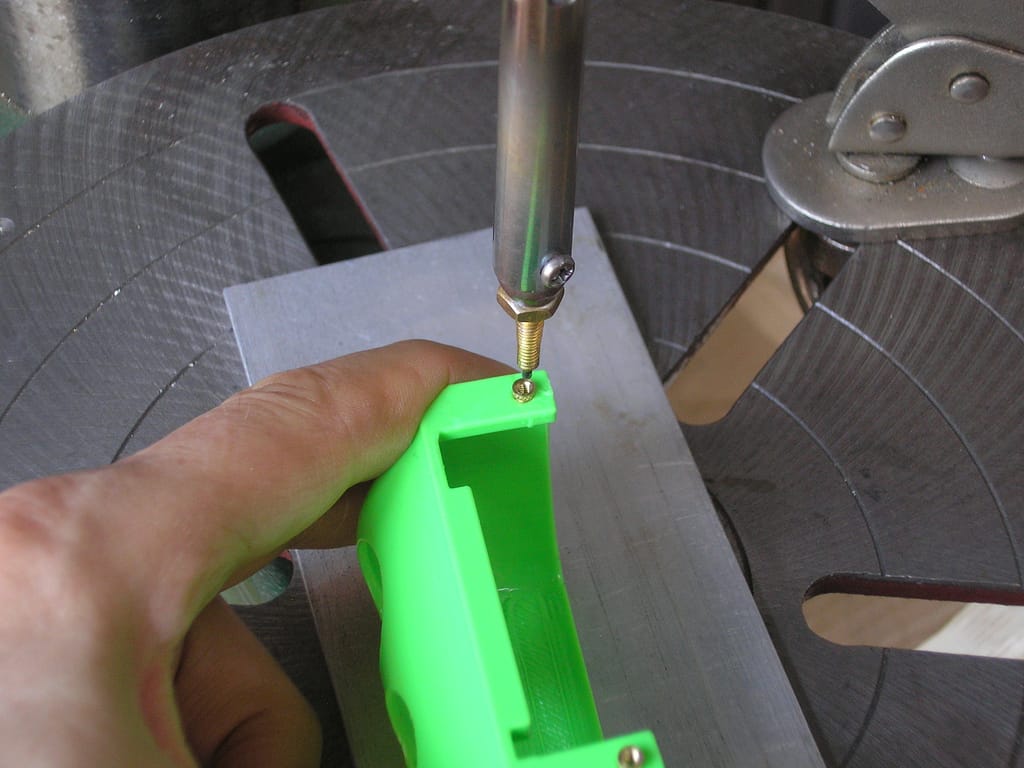
To prepare the base plate you will need a soldering iron and the #2-56 x 0.115″ heat-set inserts for plastics and M3-0.5 x 3mm inserts for injection molding. The #2-56 x 0.115″ inserts will go through the topside of the base plate (side without grooves) while the M3-0.5 x 3mm inserts will go into the bottom side (side with the grooves). Adjust the temperature of the soldering iron to around 320°C. Place an insert on top of a designated hole, then use the soldering iron to heat the insert and slowly push it into the base plate. Reference the diagram below to figure out which inserts go in which hole.
*IMPORTANT*
Keep the soldering iron perpendicular to the surface to ensure that the inserts are not going in at an angle. This is particularly important to keep the screws that go into the gears and motors leveled.
Faceplate
Repeat the same procedure as the baseplate for the faceplate using #2-56 x 0.115″ heat-set inserts.
Gears
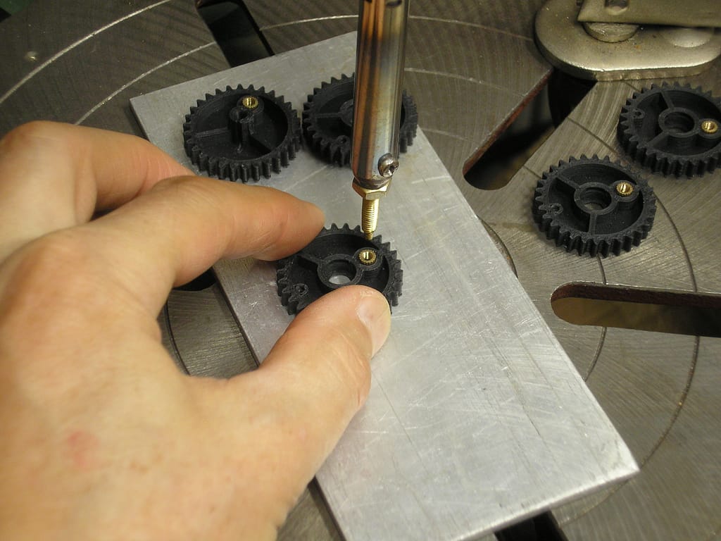
Repeat the same procedure as the baseplate for the gears using the M3-0.5 x 3mm inserts for all gears.
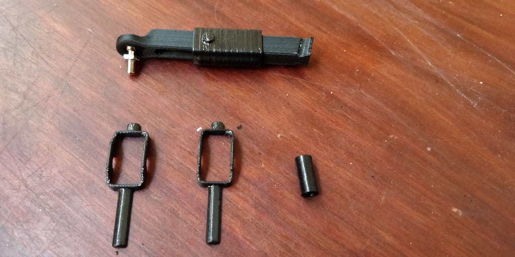
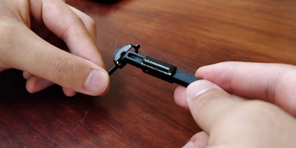
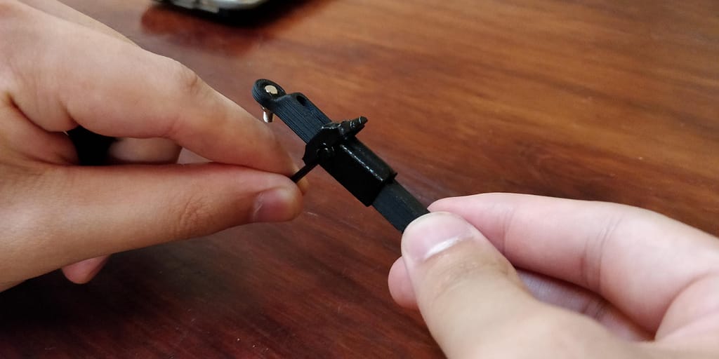
Assembling the Femurs
Run the femur through femur slide making sure the femur is being inserted into the side of the femur slide that has the extrusion. Insert 2 steel ball bearings to the top and bottom femur rails. The entry point for the balls is on the side with the ball stud.
Take 2 femur yokes and place them on the femur slide so that they enclose the extrusion. Insert the legs of the femur yoke into the femur yoke sleeve and insert the exposed leg into the designated hole on the base plate. Repeat for all 6 assembled femurs.
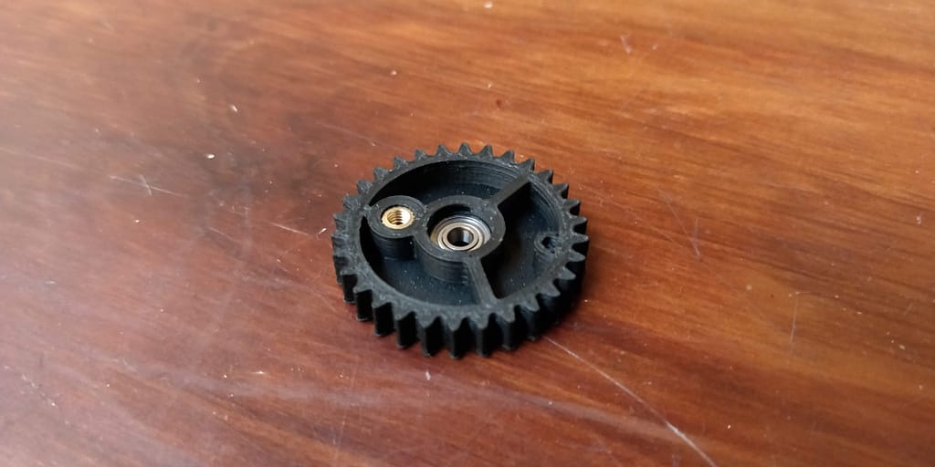
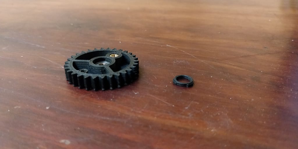
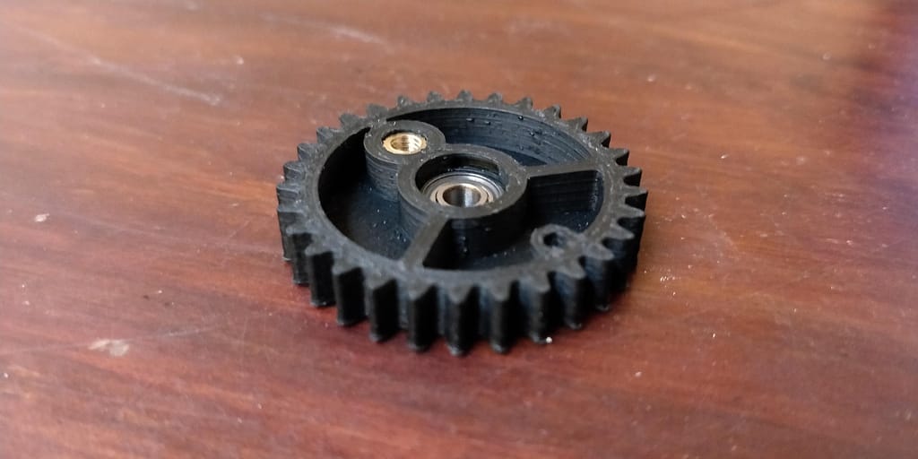
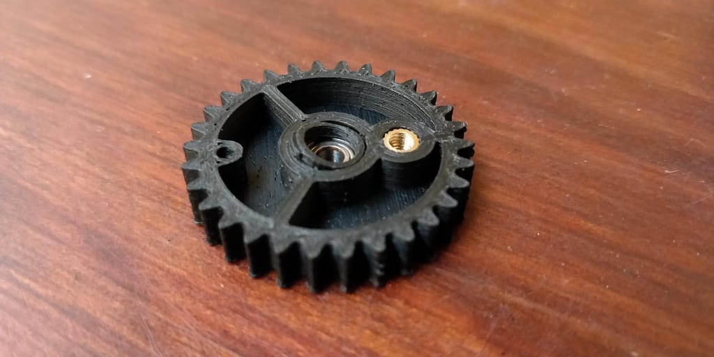
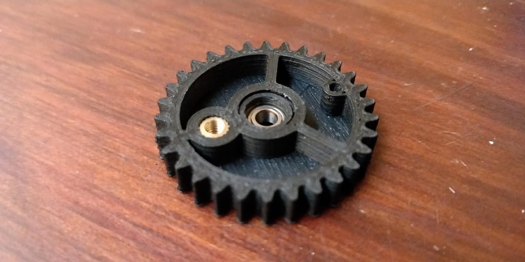
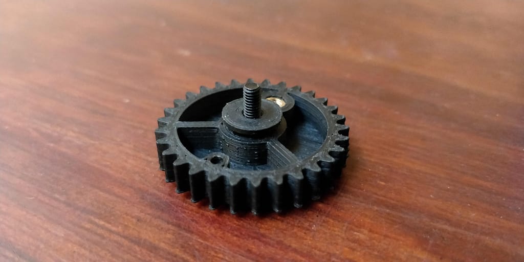
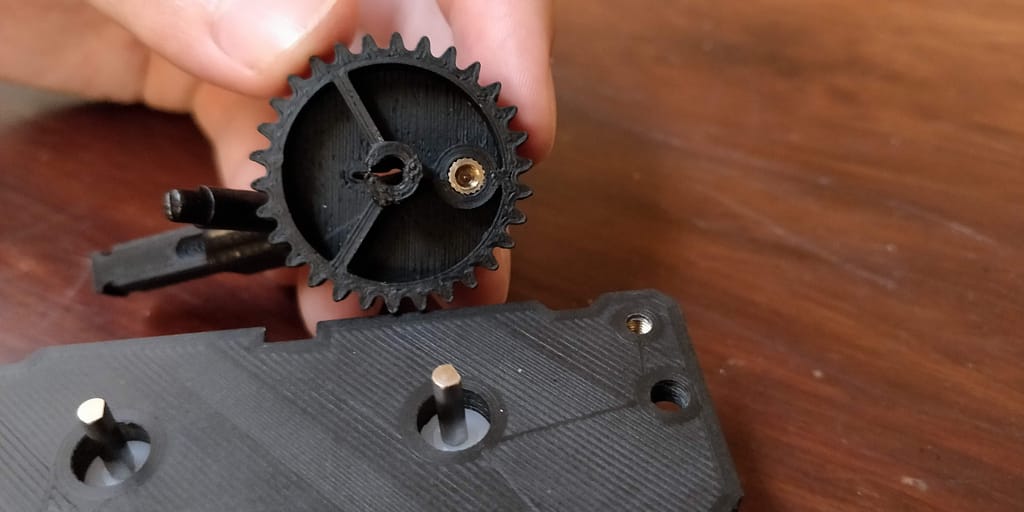
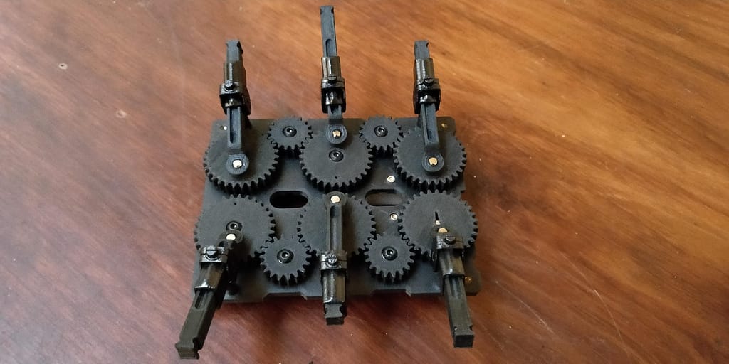
Assembling the Gears
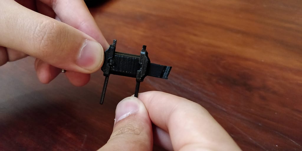
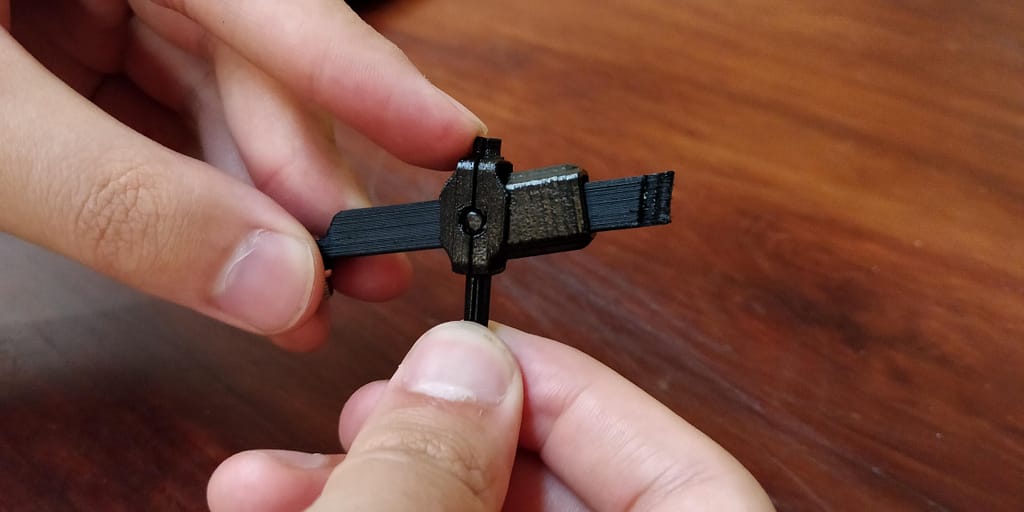
This assembly process is only for the idle gears. Place a shielded metal bearing into the slot of the idle gear. Next, orient the anchor so that the extrusions are on top so the inner part of the anchor can hold the inner race of the steel bearing. Line up the extrusions to the grooves inside the gear and slowly press it in. Be careful when inserting these anchors as applying too much pressure can break them.
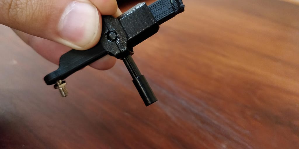
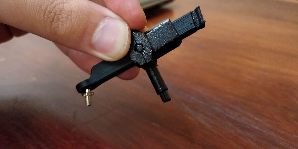
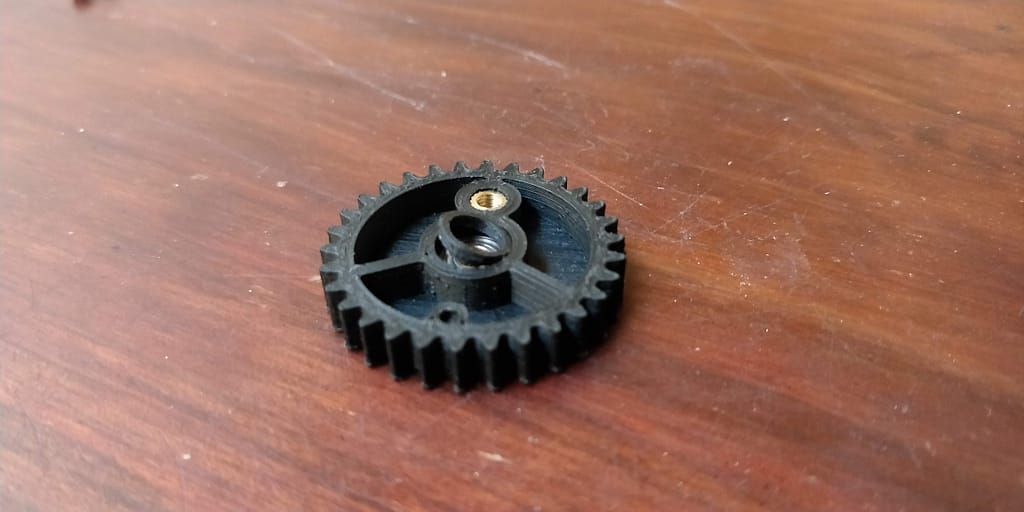
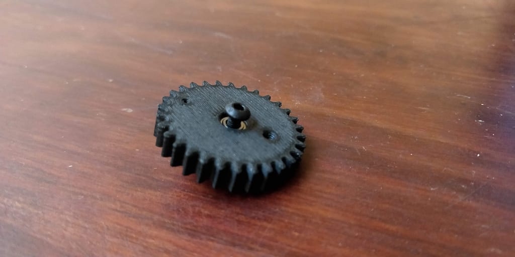
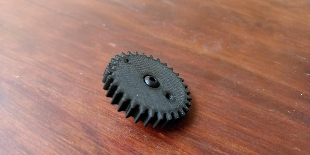
After placing in the anchor, take a gear spacer and insert it into the gear. Insert a M3-0.5 x 12mm button head cap screw through the topside of the gear and out the back through the spacer.
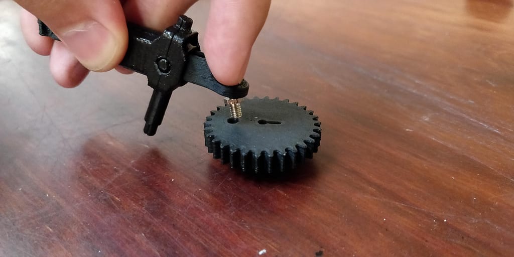
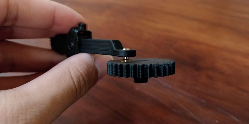
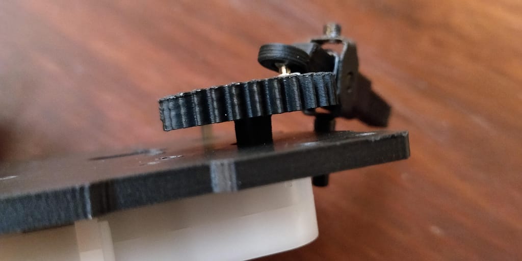
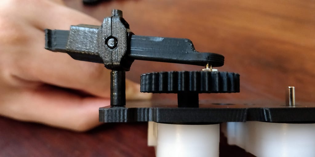
After assembling the all the femurs, screw the ball stud into all the 30 teeth idle and driver gears. Use a 5mm wrench or pliers to screw in the ball stud.
Note: If you plan to remove the bearing later you cannot reuse the same anchor and will need to print a new one to refasten the steel bearing.
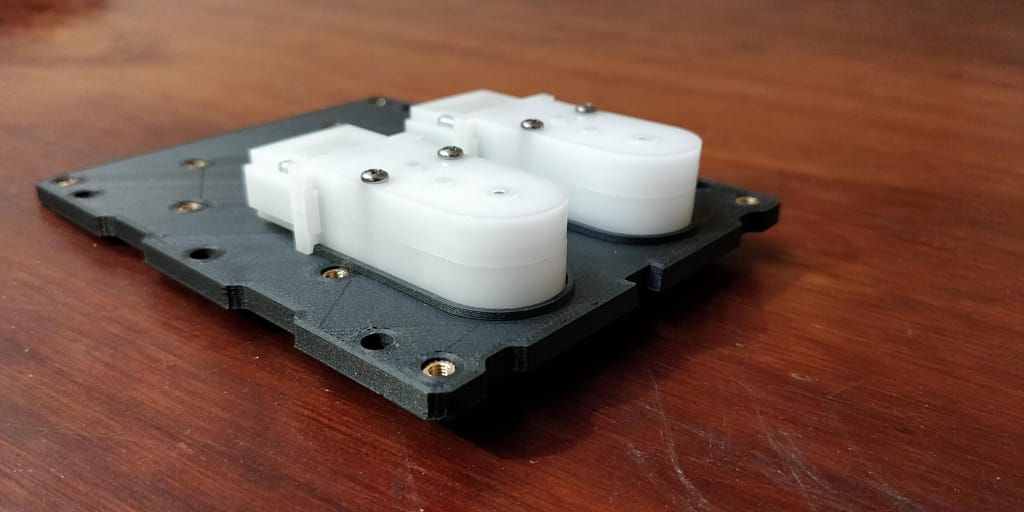
Attaching the Motors and Gears to the Base Plate
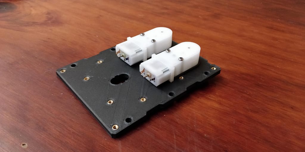
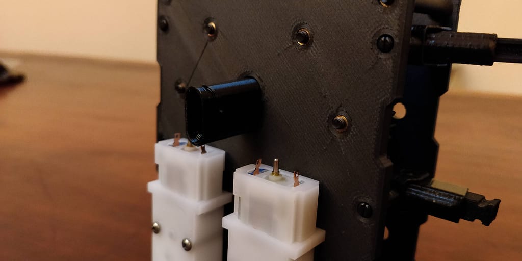
Attaching the Motors
Orient the baseplate to see the bottomside with the grooves. Line up the motors with the grooves that are on the bottom side of the backplate. Make sure that your motors’ D-shaft is going positioned to go through the baseplate. Secure the motors with #2-56 x 11/16″ pan head machine screws.
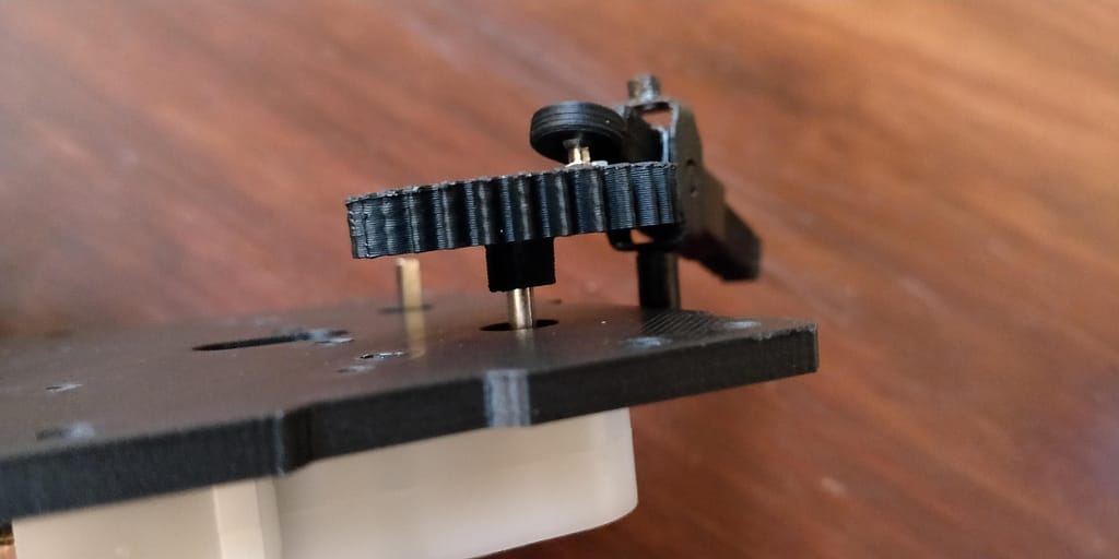
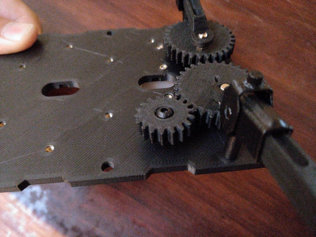
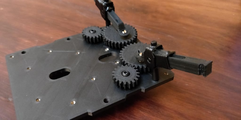
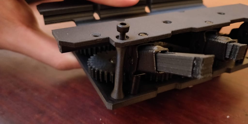
Attaching the Gears
Flip the baseplate to have the top side up facing up. Install the driving gears first. Find the 2 driving gears that have a D-shaft cutout. Match up the D-shaft cutout to the D-shaft on the motor and insert the shaft. Push the gear all the way down until the gear is secured. Next, take the posts on holding the femur slide and insert those into the post holes of the baseplate.
Now we will install the idle gears. Following the driving gear, take an 18 teeth idle gear and place it on the hole next to the driving gear. Secure the idle gear with a M3-0.5 x 12mm button head cap screw. Use a [I need to specify the size] hex bit to screw in the screw. Following the 18 teeth idle gear is a 30 teeth idle gear. Repeat the installation process for all gears. To determine the position of gears, remember that the 30 teeth idle gears will be in line with the driving gear and the idle gears are in line with each other.
Note: Keep each 30 teeth idle gear 180° out of phase from its neighbor. For example, if the ball stud of the driving gear is directly next to its femur post, the neighboring gear (the middle gear) will need to be positioned so the ball stud is furthest from its femur post. Feel free to unscrew the 18 teeth idle gears to make it easier to adjust each gear.
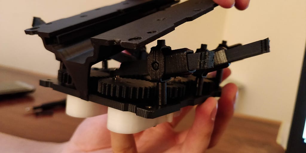
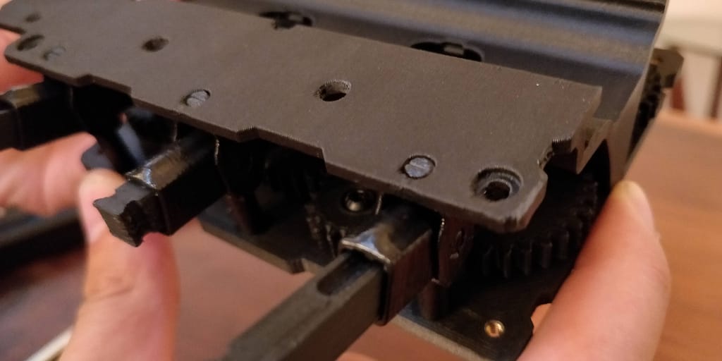
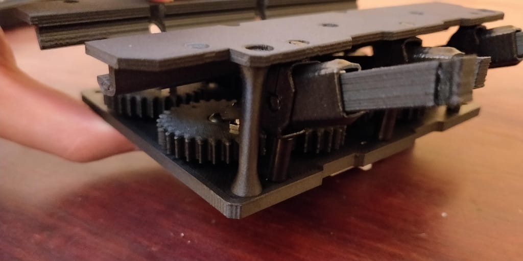
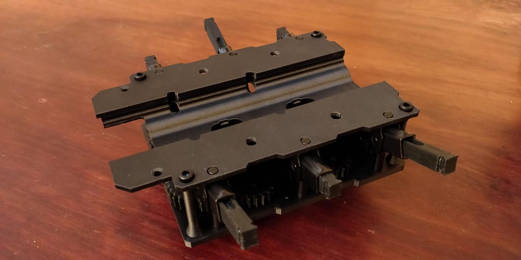
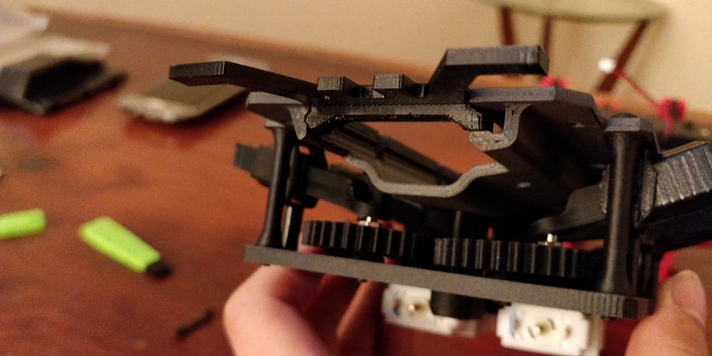
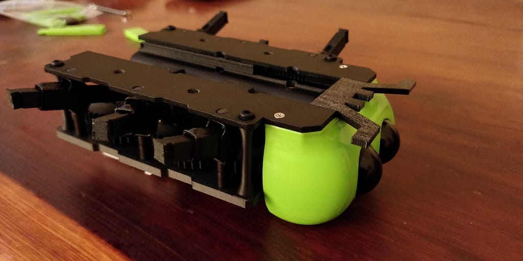
Securing the Top Plate and Cable Routing Tube
First we will install the top plate before installing the cable routing tube. Align the dovetail in the back of the top plate with the divot in the bottom plate. Slowly fit the top femur posts to the holes in the top plate starting with the posts closests to the back and work your way to the front. After all the posts have been inserted into the top plate, position the long plate spacers in the four corner holes between the two plates. Screw them down with a M3-0.5 x 35mm socket head cap screw. Insert the screw from the top plate and screw it into the post using a [I need to specify the size] hex bit
Installing the Final Accessories
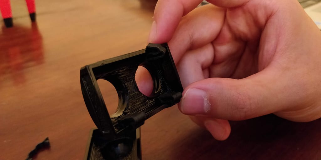
Faceplate Assembly
The faceplate is made to accommodate ultrasonic sensors or our blank eyes. First insert the spacer into the side grooves of the faceplate. Make sure the orientation of the legs of the spacer line up correctly with the faceplate. Repeat this for both sides.
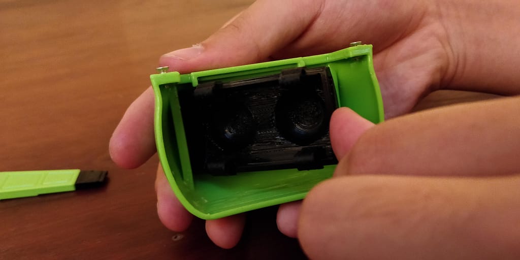
Optional: If you are planning on mounting an ultrasonic sensor then use the eyes that have the cutout for the ultrasonic sensors. Add the 4 board clips with the thicker part positioned on the inner side of the cutout. These clips will hold the sensor in place.
To insert the eyes start with pushing the eyes towards one direction of the faceplate, on one of the spacers, then slide the other side of the eyes into the faceplate.
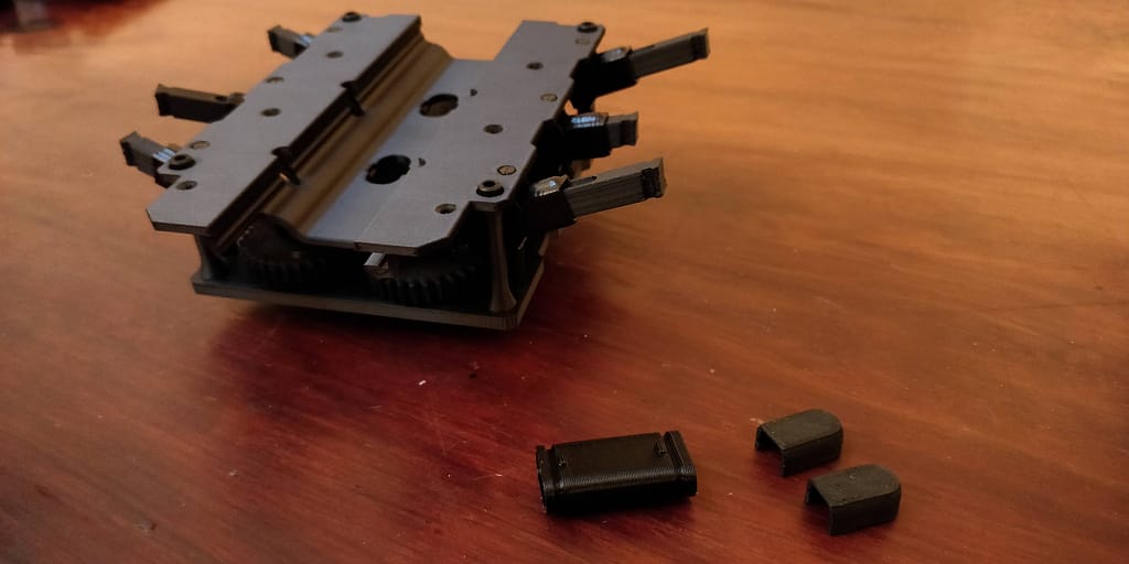
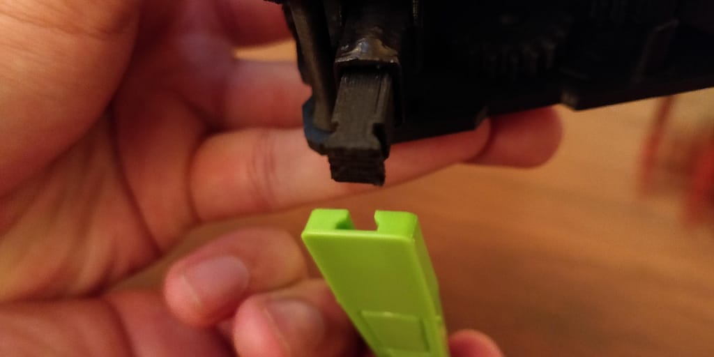
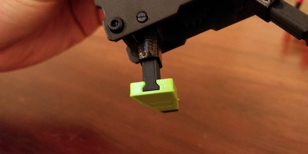
Adding Feelers and Faceplate
Insert the feelers into the front rails and secure it by inserting the faceplate. The faceplate will slide partly into the rail and will hold the feelers in place. It should be flush with the rest of the front of the top plate. The faceplate will be secured by #2-56 x 1/4″ flat head machine screws.
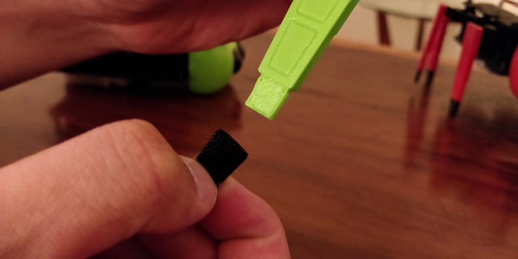
Assembling and Attaching Legs
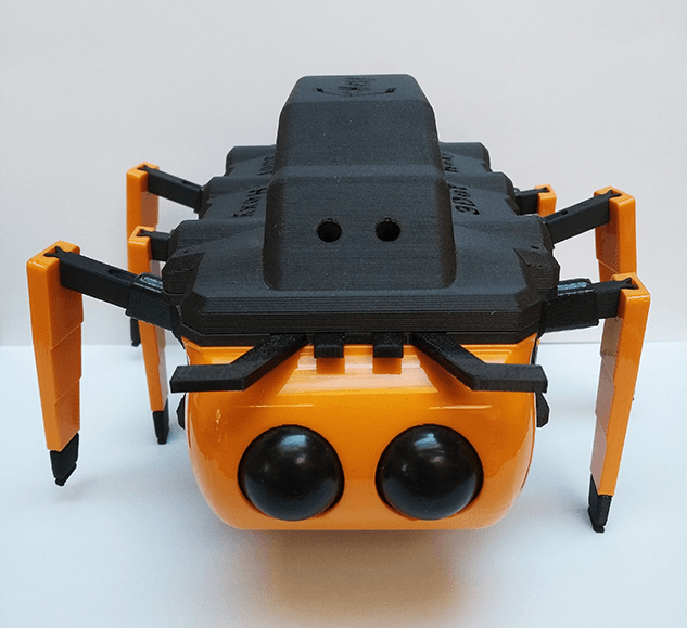
Start by fitting all the socks onto the feet of each leg. Next, match up the dovetail on the femur to the cutout in the leg and insert the legs. Repeat for all six legs. The last step is to put the shell on top of the robot.
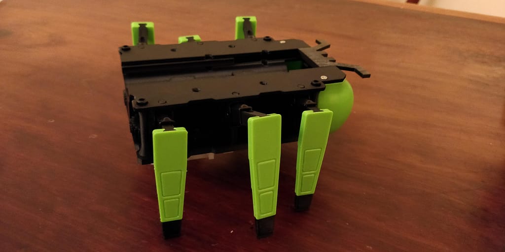
And done! Slide in a 3DoT when ready.